After publishing the first paper about harmonic distortions and how to read the technical graphs, I was asked to explain the Intermodulation Distortions as well.
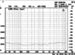
Here a typical measurement of the IM Distortion of a power amp driving 100W into 4 Ohms.
The input signal is a so-called dual tone with f1=19kHz and f2=20kHz.
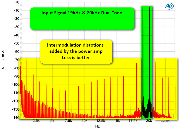
Pictures like the above can be found in “Stereophile”. This above tested power amp has very high intermodulation distortions.
As an engineer I would call such a design very non-linear (the opposite from an ideal device) and therefore it creates unbelievable counts of additional spectral lines with high amplitudes, these additional spectral lines are called IMD InterModulation Distortions.
The frequencies of the two-tone intermodulation products can be computed by the equation:
M*f1 ± N*f 2, where M, N=0, 1, 2, 3,…, whereby we think in absolute values to avoid negative frequencies.
The order of the distortion product is given by the sum of M + N.
The 2nd order is given by (f1+f2)=38kHz and (f2-f1)=1kHz
The 3rd order is given by (2f1 – f2) =18kHz and (2f2-f1)=21kHz
The 5th order is given by (3f1-2f2)=17kHz and (3f2-2f1)=22kHz
The 7th order is given by (4f1-3f2)=16kHz and (4f2-3f1)=23kHz
And so on.
So we have distortions at higher frequencies like Harmonic Distortions we know from a single tone measurement, but the difference is we have also distortion products at lower frequencies.
In the literature the IM phenomenon is sometimes called “mixing”, the distortions are “mixed down” to lower frequencies.
With more than two tones the story gets even more complicated.
One case is for instance is the output signal of a DAC with impulse optimized digital filter.
The next picture shows the Intermodulation distortion of a TRINITY DAC with a time optimized digital oversampling filter.

Even with 4 spectral lines in the output signal, the Intermodulation distortion are almost below the human hearing threshold and request even better preamps and power amps.
By the way for sampling rates of 176.4kHz and 192kHz the digital oversampling is bypassed and therefore there are only the two original 19khZ and 20kHz signal visible.

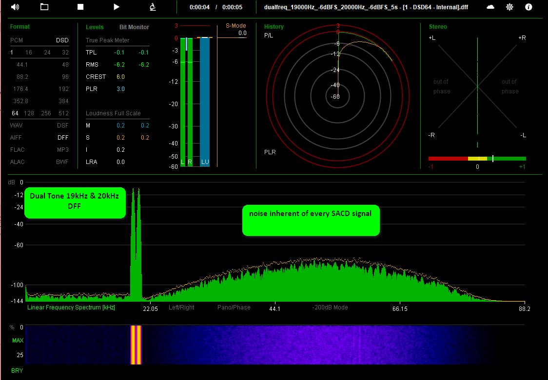
It is not obviously, but a SACD signal can generates real noise problems, if the following electronic has high intermodulation distortions.
We all know that SACD has one major problem, it has a lot of “out of band” noise, which means this noise is placed above the audio bandwidth and should be not audible.
Just to mention a PCM file does not have such inherent noise.
If such a wide band SACD signal, like the calculated signal below, goes to a preamp and power amp with high intermodulation distortions like the bad power amp example from above, it can happen that this noise is also mixed down in the audio band like intermodulation distortions and then you can hear in addition to the intermodulation distortion some additional noise.
The picture below shows the ideal spectrum of a dual tone with 19kHz & 20kHz in DFF format. As you can see the DFF format inserts this additional noise above 20kHz.
To overcome this problem of a possible down mix of the sampling noise you can use a 20kHz low-pass filter in the SACD source, which can also be an external DAC playing a DFF file or you have to use electronic with very low intermodulation distortions.
By the way, in some SACD player you can select an additional 20kHz low-pass filter.
The TRINITY DAC can play SACD signals without any problems and the TRINITY preamp and TRINITY power amp are ultra linear and have no problems to playback unfiltered SACD signals.
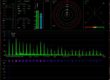
The picture bellow shows the Intermodulation distortion of the Preamp of the Reference Line, whereby the CH2 shows the input signal, which comes from the audio analyser and CH1 shows the output signal of the preamp.
First we see the spectral line at 1kHz, but this line is already in the input signal, which is generated inside of the AP 55x audio analyzer.
For the dual tone measurement this audio analyser has to use two internal DACs, which are not as good as the low distortion sine wave generator.
I you look very carefully you will see the blue line is overlaid by the red line.
Or in other words the intermodulation distortions of the TRINITY Pre and Power are so low, that I cannot measure them, caused by the limitation of the current available measurement instruments.

The target of these papers is to make you sensitive, how important all these measurements are.
Measure means to compare, if you want produce devices of identical performance and quality, you have to measure every parameter of every device and that is the reason why each TRINITY device comes with a measurement protocol.